Electricity and Electrical Devices
|

The following lesson was shared by InkSmith 3D Printing.
|
Lesson Overview:
In this activity, groups of 3-4 students will collaboratively design, build, test and modify a capacitive stylus for use with a variety of touchscreen devices.
Evaluation Criteria:-Overall object heights should be no longer than 20 cm.
-A cap should be provided to protect the tip of the device. -Group Bonus; Conductive components are ‘hidden’ within the scope of the overall design so as to not be viewed by user. -Individual Bonus; Opportunities for length and width modification have been provided so as to increase the ergonomic fit for the user. |
|

By the end of this project, students will:2.6 - Use appropriate science and technology vocabulary including current, circuit, conductive and energy.
3.3 - Identify materials that are good conductors of electricity. 3.6 - Explain the functions of the components of a simple electrical circuit. |
By the end of the lesson, groups will:
|

By the end of the lesson, students should be able to:
|
Materials Required:

Resources:
There are extensive resources available on both stylus reviews and DIY builds. The discussions around conductivity are natural. It’s fun to watch something you’ve built function like a real world product! Some of the best selling devices are not necessarily the most effective, and some of the most obscure ones are the most innovative. Exploring what’s out there will really allow students to rise to the challenge on this task. Encourage ideation, creation and rapid prototyping with your students. The best designs are the ones that fail fast!
Below are some suggested resources related to stylus design:
Below are some suggested resources related to stylus design:
|
|
|
|
Lesson Plans
Getting Started:
List on the board or in a hand-out the ‘Specifications’ which each group must meet to complete their design for the proposed structural mechanisms. This list can be modified to suit different classroom setups, evaluation objectives, time, and available materials.
Classroom Setup:
-Students will be grouped with 3-4 peers as needed.
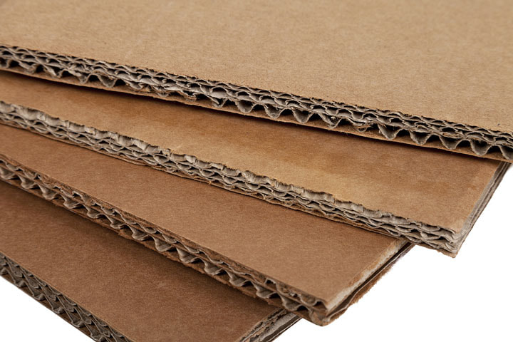
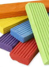
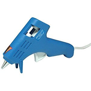
-Allocate specific areas for each group to work, as well as the necessary prototyping materials (cardstock, plasticine, hot glue gun/glue sticks)
-Provide all materials to each group and have them label them with a group name.
Each group will:
Creating The 3D Model:
Students can use any available 3D modelling software to design their objects. For a first experience -- or when loading software onto classroom computers is prohibitive -- consider a browser-based solution such as TinkerCAD (www.tinkercad.com) or Onshape (www.onshape.com). For career building, professional-grade software such as SolidWorks, Fusion or Inventor are preferred if these don’t add undue time pressures or licensing cost.
Introductory lessons for both TinkerCAD and Onshape are available as tutorials inside the respective software. It is assumed that for this challenge project that the students are already familiar with some form of modelling software.
3D Printing:
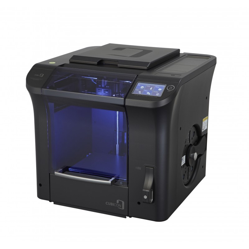
When a group’s 3D model is complete to specifications students will upload their files to the Cubicreator software, slice and print.
Students will need to be careful to ensure that models are properly supported, have adequately designed-for overhangs and are sized correctly to fit the build plate. Students will also be required to adjust for outer hull thickness (aka “shells”), infill density and infill pattern. Students may be permitted to print multiple iterations of each design depending on the availability of supply materials and printer time.
List on the board or in a hand-out the ‘Specifications’ which each group must meet to complete their design for the proposed structural mechanisms. This list can be modified to suit different classroom setups, evaluation objectives, time, and available materials.
Classroom Setup:
-Students will be grouped with 3-4 peers as needed.
-Allocate specific areas for each group to work, as well as the necessary prototyping materials (cardstock, plasticine, hot glue gun/glue sticks)
-Provide all materials to each group and have them label them with a group name.
Each group will:
- Allocate different jobs for each member of the group
- Create mind maps and drawings on newsprint of possible ideas
- Individually design multiple solutions, then collaborate and discuss benefits of each
- Collaboratively select the best design solution for the stylus
- Work effectively in a team to complete peripheral tasks quickly
- Output their selected 3D printed objects then evaluate and iterate through testing
- Individually and constructively evaluate other peer contributions to the project
- Discuss and document group successes and challenges in both teamwork and solution
- Discuss the benefits of experiential and experimental learning
Creating The 3D Model:
Students can use any available 3D modelling software to design their objects. For a first experience -- or when loading software onto classroom computers is prohibitive -- consider a browser-based solution such as TinkerCAD (www.tinkercad.com) or Onshape (www.onshape.com). For career building, professional-grade software such as SolidWorks, Fusion or Inventor are preferred if these don’t add undue time pressures or licensing cost.
Introductory lessons for both TinkerCAD and Onshape are available as tutorials inside the respective software. It is assumed that for this challenge project that the students are already familiar with some form of modelling software.
3D Printing:
When a group’s 3D model is complete to specifications students will upload their files to the Cubicreator software, slice and print.
Students will need to be careful to ensure that models are properly supported, have adequately designed-for overhangs and are sized correctly to fit the build plate. Students will also be required to adjust for outer hull thickness (aka “shells”), infill density and infill pattern. Students may be permitted to print multiple iterations of each design depending on the availability of supply materials and printer time.
Assessment
As suggested above in the “success criteria” section, instructors may evaluate this project based on any criteria required. However, it is suggested that the following be heavily considered as part of the overall success metrics for each group:
NOTE: Through conversation and observation, groups should be able to confidently talk about the parts of their models, the dimensions they have used and the solutions they have come up with to solve various problems throughout the design process. Write-ups are welcome, but often rich information comes out of these anecdotal conversations. Video recordings can be a great way to capture this information so that a Teacher/Instructor can return to review at a later date.
- Overall object heights should be no longer than 20 cm.
- A cap should be provided to protect the tip of the device.
- Group Bonus; Conductive components are ‘hidden’ within the scope of the overall design so as to not be viewed by user.
- Individual Bonus; Opportunities for length and width modification have been provided so as to increase the ergonomic fit for the user.
NOTE: Through conversation and observation, groups should be able to confidently talk about the parts of their models, the dimensions they have used and the solutions they have come up with to solve various problems throughout the design process. Write-ups are welcome, but often rich information comes out of these anecdotal conversations. Video recordings can be a great way to capture this information so that a Teacher/Instructor can return to review at a later date.
|
|